3S: Coil on Plug Installation / Fixes

Originally, the plan was to take the Stealth down for both the drive-by-wire (DBW) and coil-on-plug (CoP) installations at the same time, but as I was doing it, I realized there wasn’t much duplicate work and that it would be better to tackle one system at a time if any problems arose.

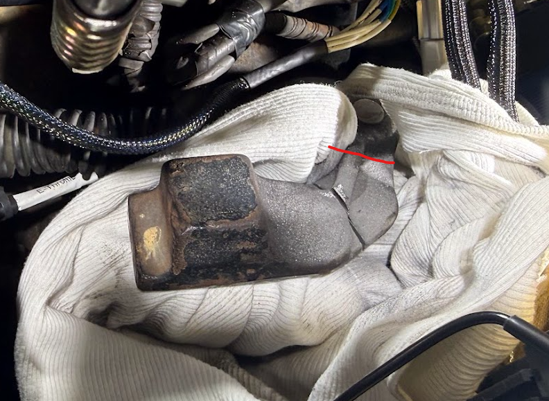
Well I wasn’t exactly planning on doing the CoP so quickly after the DBW, but while driving the other day I noticed coolant leaking from the thermostat housing… and of course it was probably the hardest hose to get off…

Leaky coolant line that goes to the rear turbo. The part that leaked was in between the crimp connector and the AN6 fitting

So to get that off I had to remove generally everything I needed if I was going to install the CoP, so I figured “while I’m down there” (the curse of all project cars)…

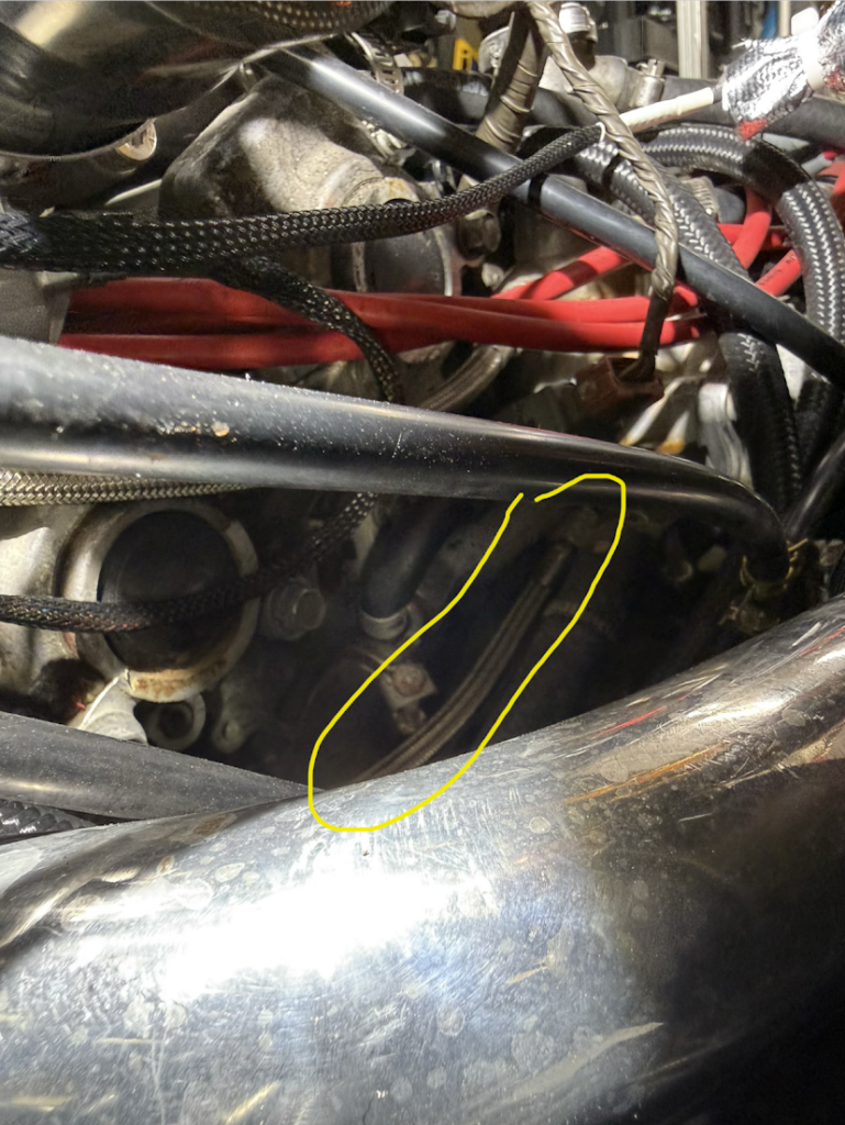
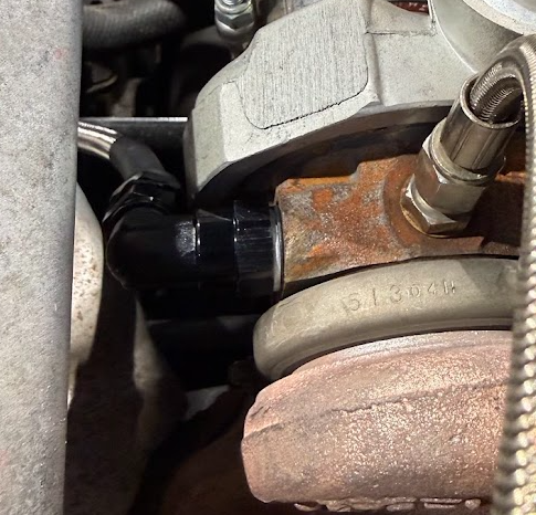
Rear Turbo Coolant Line Replacement:

Up to this point all the “an lines” I’ve made have been nylon braided ones and never a “PTFE” one. Had to do a little research on this, but really it’s pretty easy to do thanks to YouTube. Although the super thick wire cutters I used for the Nylon one was no match for this. So I had to resort to regular cut off wheels. I also didn’t see any reason to stick with a Banjo bolt. I talked to a few colleagues and none of us could come up with a reason we want to restrict flow. Per AI, a regular right angle connector would flow about 60% more coolant than the banjo bolt and since this is just cooling a turbo that gets notoriously hot, I figured that was a good thing.

A replacement PTFE hose has entered the room…

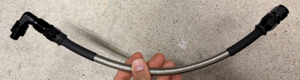
Installation of this went fairly easy. There were cheaper options available if I wanted, but now I have extra PTFE tube, extra connectors and everything. I thought about replacing the rear one as well but ultimately decided I wasn’t going to. I seriously have my concerns about the M12x1.25 right angle connector not leaking, but so far so good.

When I installed this, I had the AN line already tightened onto the elbow. I didn’t think I would have space to tighten the AN fitting onto the elbow and I appeared to be right. Thankfully there’s just enough clearance to fit the elbow on!

CoP Installation

Half the problem with the CoP installation was the fact I bought the kit used. In retrospect the amount of items missing and questions I had about it I would have been better off just buying a new one. There were bolts missing, spacers missing, no “cover” plate, etc. I also received “Hitatchi” CoP vs the Denso that R’Venge lists, but they appear to be the “Prius” ones also… so maybe just a swap? Who knows?

I determined the “spacers” were roughly 1/2″ OD x 1/4″ ID and 1″ in length. I bought these off Amazon and they appear to be a pretty good match. Was also missing the free bolts from it, they appear to be M8x1.25 and 45mm in length or so. I was able to re-use two of them, but they are barely getting any grip.

I followed the R’venge Installation Guide / FAQ and in general it was pretty accurate with few “gotchas”.

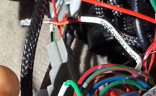
I also “hotwired” via relay the CoP so it got as much voltage as possible. I’m not the most happy with the engine bay wiring, but it wasn’t bad. Throughout this process there were a few times I was combining six wires into one (voltage, ground, and tach signal). What I think is the best method for this is the “Open Barrel Splice” and since I didn’t take any pictures of this, here is a great video from Motion Raceworks that shows how to do this.

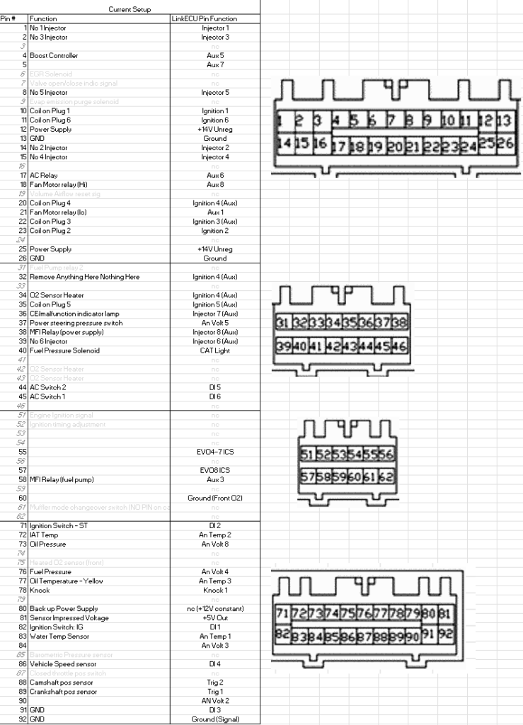
The other thing I did in this installation was run all the Ignition wires directly to the ECU instead of through the factor PTU wires for three of them. I just felt like giving it a new direct wire could save me headaches later and since I was already going down that path it was best to just go ahead and do this. I tied them directly to the LinkECU Pin Function that was for that item, so Cylinder 1’s CoP went to Ignition 1, 2 to 2, etc. I am not sure in the LinkECU if you can change this outside of changing the firing order, but I figured this was the best case to just keep them tied to the right cylinder. If you go this route you’ll need new pins. I think I only needed the “smaller pins” but if you are ordering from Digikey you might as well grab some of the larger ones as the injectors are all the larger ones…

Small ECU Pins: TE 175265-1 (Most of the ECU Pins)
Larger ECU Pins: TE 175269-1 (ECU Pins 1, 2, 3, 12, 13, 14, 15, 16, 25, 26 )

My “heavily” modified ECU Pinout with the connector right next to it. This image was vital for me working under the dash plugging everything in.
Please remember to “cap” off any ECU pins you pull out. My preferred method is to use a label maker with 6mm heat shrink labels and to label them also. Then just heat shrink it over the actual pin. In the above image I eventually heat shrinked the “Turbo wastegate” over the pin. In the future if I were to do it again I would probably add what PIN it was originally.
Within LinkECU the settings to change are pretty easy. I changed it from Wasted Spark to Direct Spark and you need to change the firing order, prior to this it was Wasted Spark and firing order of 1-2-3-1-2-3.

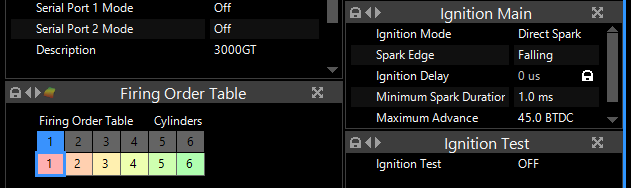
R’Venge provides some starting Dwell times, went off “Prius” ignition dwell times I found online, but I’m not publishing it as I don’t know if it’s accurate or not.

Car all buttoned back up and adding coolant. I found this little “coolant” filling system on amazon a long time ago, none of the adapters fit directly, but I was able to find a way to make it work. This is before I turned the car on so I was only adding distilled water.

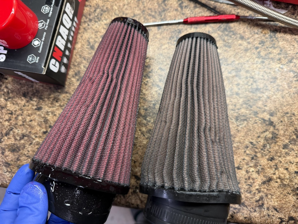
Bonus Round – “While I’m down there”

This is the shifter counter-weight for the six speed transmissions. One common problem is it hits the FMIC pipes in 4th & Reverse. I only had a problem with reverse. I cut it where you can clearly see with a oscillating multitool (as I felt it was the cleanest option), if I were to do it again I would cut on the redline instead.
I also finally cleaned my K&N filters. These filters have been on the car since roughly 2018, and have never been cleaned. While they didn’t drive that many miles (about 3,000) they have sat in dusty areas and everything. I bought the K&N Filter cleaning kit ( 995000 ) and used the cleaner part twice. Even after that the filter didn’t really look clean on it’s own, but once you add the oil it really turns red and looks good.

3S: Drive by wire installation

Watching / learning a lot about how to tune the car on an aftermarket ECU (LinkECU G4X) has been a process and one of the things often mentioned is how DBW is the best way to control idle (compared to stepper motors, etc) and it also reduces potential air leaks. I also realized if I converted to DBW, that would free up several new AUX channels on the ECU for my Coil on Plug install that is coming later this winter…. so I went down the path…

Throttle Body Installation

The Bosch 68mm throttle body is said to be a “direct” fit and just needs to be drilled out… and generally this is the case. The throttle body is already set up for M6 bolts, while the 3S Plenum is M8. So you need to drill this out to about 9mm. I had two drill bits that were close in size, I tried the smaller one 11/32″ (8.73mm) and couldn’t install it still, and ended up using 3/8″ (about 9.5mm) and it worked fine. Once you do that, the next problem I ran into was the stock bolt fitment… they technically fit but I couldn’t fit a socket over them. So I swapped them out for M8x1.25 55mm socket head caps and used some purple thread locker (retainer). The next problem I ran into was the bracket that holds the plenum up ran into the throttle body motor so I had to remove that (which was a pain if you don’t want to remove anything else).

I covered up the connector and the whole housing to prevent any metal shavings from getting into it while drilling it out…
Very tight fitment with the stock bolts and the socket on the bench. When trying to install it on the car, it wouldn’t fit…
Custom 3D Printed TPU Gasket installed (linked below).
Brackets which I removed. The one on the back of the valve cover had three bolts, 2 12mm sockets and 1 10mm socket iirc. The steel braided oil lines to the turbos are pretty rigid which made the removal more annoying. If you pulled the plenum off it would have been easier….
Finally installed with the brackets removed.
All buttoned up. The previous silicon coupler fit, but it was tight. I had to increase the size of the t-bolt clamp. The previous one was 67-75mm (iirc) and this is just a tad too big. I have a 73-81mm ordered. I do not plan on replacing the silicon coupler though.

350Z Pedal Installation

I bought the pedal adapter from Outsider Garage over the EvoSpec one as the pedals were much more commonly available and significantly cheaper I think I paid $55 shipped for mine (used) versus most evo ones were close to $200. The pedal adapter was only $45 which was cheaper than I could make / design this myself (as I was going down this path originally).

There is a piece of folded medal on the back of the 350z pedal that needs to be removed, otherwise you only have about 1/2″ – 3/4″ travel on the pedal (probably about 30% it’s total capacity). I removed a good amount, and now the pedal hits the floor. I would argue I have about 80-90% the total throw now, and once you get it into the ECU you calibrate it and so it’s not a big deal. I do wish the angle on the adapter was a little steeper so that pedal stuck out further, but it is what it is. I know outsider garage sells a replacement pedal for this, and maybe that fixes some of my complaints.

The adapter shifts the pedal to the left a bit as it’s more inline with where the stock one was.
You can see it sits a bit lower than the brake pedal, but it’s in a good position (horizontally)
Back of the pedal trimmed down.

Wiring

Wiring was my least favorite task of this whole effort. I really didn’t know where I wanted everything pinned to in the ECU, but I eventually came out with a solution that cleaned it up a little, but didn’t require me to re-wire everything. I had a lot of wires on my expansion “ports” for the ECU previously but I moved them to the main harness and used the expansion port for the DBW as it was designed for that. The throttle body and the pedal both need 2 sensors each ( redundancy ), and the TB needs two (three) AUX ports.

Throttle Body Connector is a Tyco Electronics Micro Quadlok System (TE MQS 6 Way). I originally purchased this from Haltech as it was convenient, but they are expensive and don’t give you any extra pins and I messed up the first one which was annoying. You’d think for $16 they could include an extra pin that only costs them pennies. Anyways it used a lot smaller pitch crimp, I don’t recall which exactly it was, but it was around 1.6 in size based on the “Engineer” crimper I have.

The pedal I bought came with a pigtail that was long enough for me to swap it over to a TE Deutsch DT connector which I use for all the connectors I can. While it’s a bit larger in size, it’s a good strong water proof connector. I am 99% positive the Nissan 350z is a Sumitomo MT branded connector. I have linked it below in the event you need it.

I’m not going into the tuning process at all. That’d be a whole discussion by itself. I will admit I messed up one setting when I first turned it on. I changed everything to the throttle position…. except my “startup offset” which was set to 10, which meant it added 10% throttle to the idle base position… so the car idled at 3k RPM on a cold engine… thankfully that was an easy fix, but I rather not idle at 3k on a cold engine…

This is my overall pinout. At the point of this post, I have completed everything in Part 1. The left column is where it was prior to the install, the yellow highlight is things that are pins that have moved from their stock location. The orange ones are the proposed changes for each “part” of the upgrades this winter. Hopefully Part 2 will be all that I ever have to do for this car [we know it won’t be].
This is my expansion ports on the Link G4X Plug-in ecu. I never really thought I was going down the DBW path and didn’t realize that connector 2 was really made exactly for the DBW setup… so that’s why i had to move most of my sensors to the main harness.

It Runs!

Testing out the pedal and throttle.
Actually running!

Parts List:

Bosch 68mm Electronic Throttle Body – 0 280 750 156
Throttle Body Gasket (Makerworld)
Outsider Garage 350z Pedal Adapter
Nissan 350z Pedal (with pigtail or Sumitomo MT-6S-3)
TE 6 way MQC (OEM P/N: 1-967616-1)
M8x1.25 55mm Socket Head Cap Bolts (4x)
Mishimoto 73-81mm Constant Tension T-Bolt Clamp

Disclaimer: This is just where I bought stuff from based on prices and shipping times. You can probably find cheaper / better parts if you look around more for some of these items.